Trains and EEG
I had this blog post as a draft for nearly a year now… and finally here it is: In my last lab we moved buildings. Good scientists we are we did measurements to see if the system works as intended…
The EEG Systems
-
- An active 64 electrode system from BrainProducts called ActiCap
- A passive 128 electrode system from ANT, a tmsi REFA-8 with actively shielded cables
- A passive 128 electrode system from ANT, eegosport with actively shielded cables
Disclaimer: All data shown here are from different subjects. Their individual alpha-peaks etc. will differ, we also switched methods a bit
ActiCap
We measured 2 subjects with the 64 electrode system. When we checked the frequency spectrum we were very worried.
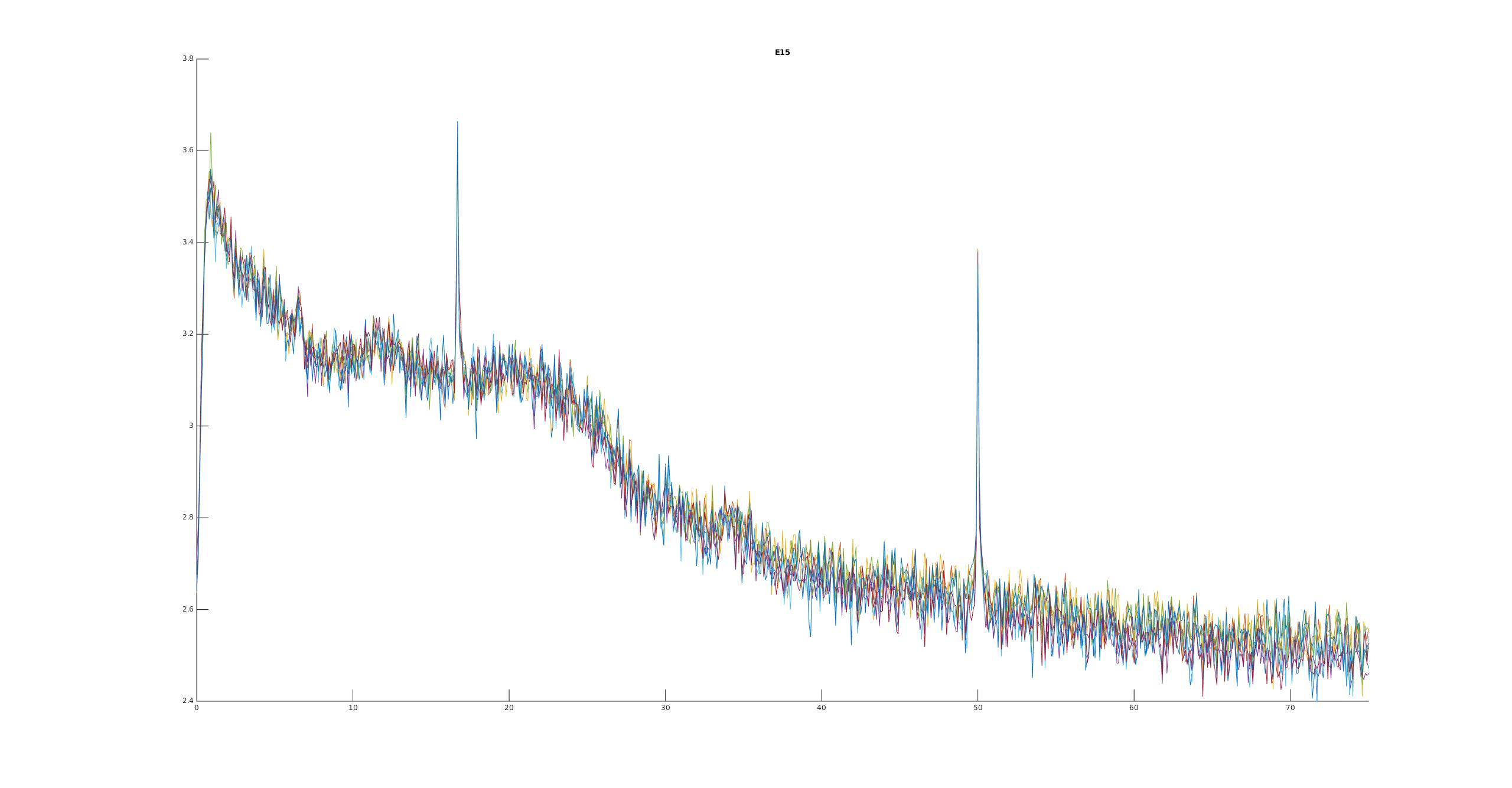
Besides the typical 50Hz artefact that we know, one can clearly see a $16 \frac{2}{3}$ Hz peak in the beta-band. The artefact is very strong and variable over time.
This can’t be right? So we recorded another subject, just to be sure. We also switched analysis methods a bit
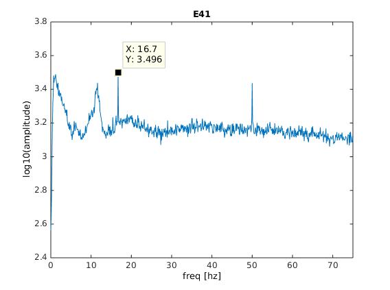
Same thing!
Side remark: The ‘activeShield’ button did not improve the shielding (plots not shown, the support told us that the activeShield function is more thought for passive electrode systems, not our system).
ANT/TMSI REFA-8
Single Amplifier (64 Electrodes)
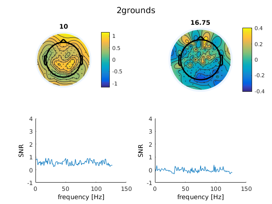
We then measured a single subject with the ANT system with a single amplifier.
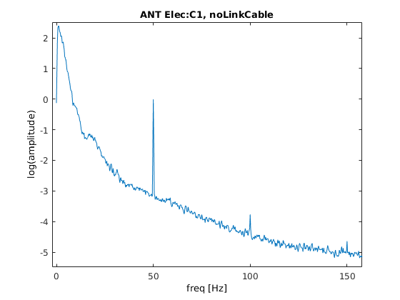
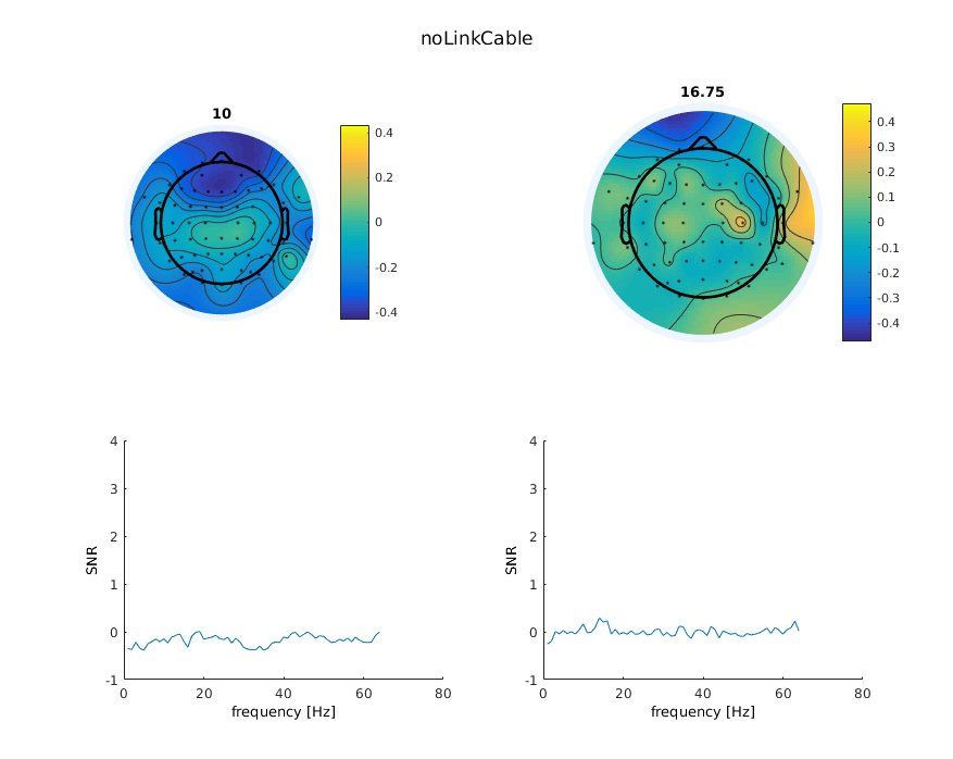
All looks fine here for now… On the second plot, we introduce the signal-to-noise (SNR) index, which is simply the current frequency-bin divided by neighbouring bins (the average of $n_{-12}$:$n_{-2}$ & $n_{+2}$:$n_{+12}$). This will enhance peaks in the spectrum. As we can see, we do not see any peaks anywhere, all is fine with 64 electrodes.
Two Amplifiers (128 Electrodes)
At first we thought, cool! ANT with active shielded cables is perfect, we will just not record with the brainproducts system. But ANT/tmsi allows to “chain” two amplifiers together to effectively get 127 electrodes. That is, the amplifiers share a ground electrode and a single electrode is bridged, so that the data can be referenced to a amplifier-common electrode. When we did this the following picture emerges:

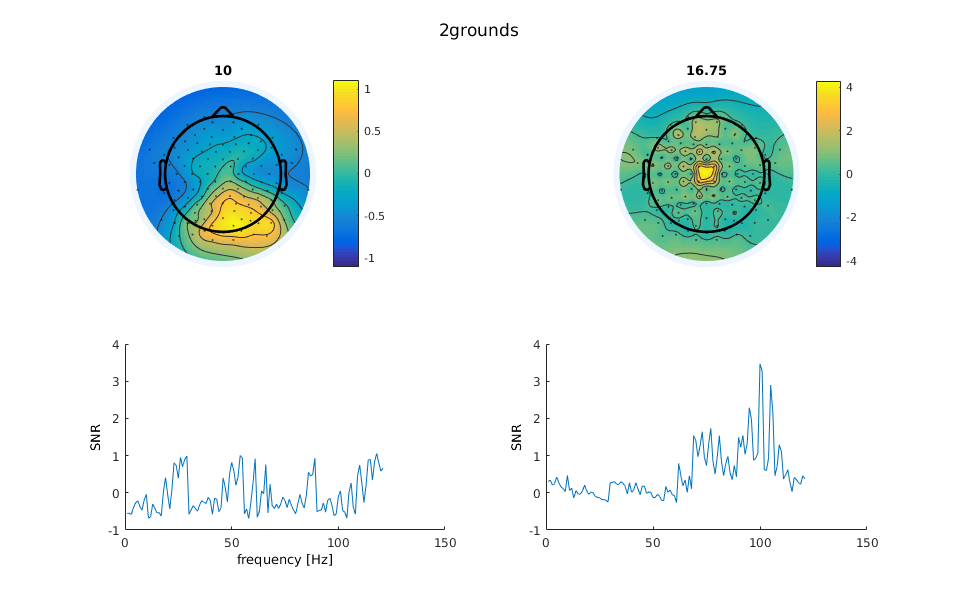
The 16 Hz is back! :(. The electrode depicted in the spectrum plot is from the second amplifier. In the lower right panel we can see, especially in the second plot, that the second amplifier has a lot of 16Hz artefact but not so much in the first amplifier.
ANT eegosport
We much later received an ANT eegosport for testing purposes. Unfortunately for us (and ANT because we did not upgrade ;)), the artefact was also present with comparable strength. Here an interesting new phenomenon arised: when flipping the amplifiers upside down, the artefact switched from channel 1-32 to 33-64 or vice versa.
Typical artefact behavior
The artefact was non-stationairy over time (sometimes its there, sometimes not, stronger, weaker …). Most often observed in the second amplifier, sometimes in the first. The artefact also was stronger (relatively) around the reference electrode. It does not depend on exact placement in room. We tried a lot of factors, at some point even wrapping things in foil – it did help a bit!
What the hell is going on?
Turns out, the new building is quite close to train tracks. In Northern Germany most trains are powered electrically using overhead lines. Germany uses $16 \frac{2}{3}$ Hz to power these lines. So sometimes when a train comes along we have an artefact. Because we did not want to time our experiments to the train schedule (we a) thought about it, but the DeutscheBahn does not give away information when trains are coming and b) the artefact is not _always_ strong when a train comes, but only sometimes, also not train dependent – but who knows…)
What can we do against it?
It took us the most part of the year (with lots of discussion with ANT & TMSI) to figure out, where exactly the artefact is induced into the signal.
Our solution
- Keep the cables as close together as possible, all in one orientation. Because the ANT REFA system allows the ~10cm cable to go into various direction, the common-noise which influences these channels can be slightly different. If the electrical field / artefact is strong enough, this slight differences will show up in your data. Thus always keep all cable very similar. We now “comb” the connector cables
- Keep the cables parallel to the field-lines of the electrical field. I.e. don’t put your cables parallel to the elongated electrical source, this will induce stronger effects. We now lead the cables to the top, so inline with the electric field
- If you use a cascaded system, the reference-electrode that links the two systems, has to follow both strings of electrodes. I.e. you have to guide it along the connector. If you fail to do so, there will be stronger artefact in one than in the other amplifier (depending on how the cable lays relative to the artefact electrical field). We now take care of this.
Combining all these measures helped us enourmously to reduce the artefact in a stationairy setting. For mobile recordings this will be tougher.
Debugging Lessons Learned
It took us a long time to figure out how to measure the artefact reliably and how to manipulate the system in order to study the artefact. Here are some lessons learned:
- A waterbucket+salt (=> a head without needing a human) is your friend. BUT: We tried this earlier and failed because the system was DC-maxing out (no signal in range). This was because we put in the whole ground electrode (which has a zink-connector) and not only the tip (AgCl). This gives very large DC offsets due to the zink contact and you cannot measure.
- Making turn around times super fast. This allows for more tests and easier replication of supposedly found effects. A online/live-script that shows us the current 16Hz power was very helpful here but took quite some programming to get smoothly.
- You need to show a lot of own initiative, support can help you, but not save you. This problem was very specific for us, a general solution did not exist
- If there is a non-stationairy noise source, it is very helpful to monitor the artefact with one amplifier while modifying things with the other amplifier. Only like that can you be sure that the artefact occured / your modification actually changed something (and you did not just measured in a low-artefact regime). An interesting phenomenon we saw, was that on one day after ~19.00 the artefact vanishes. We are not sure why this is the case, because trains were still running. The trains passing by do not produce a reliable effect in itself. We think this is because the power to the grid is turned on whenever a train is on the whole section, with a section being multiple kilometers long and possibly reaching into the trainstation (but we do not know this before).
Methods
We detrended or highpass filtered the data at 1Hz. Welchs estimate does not like DC-drifts. We generally either bandpass filter the data, or use the pwelch algorithm. We also employed the TMSI matlab-toolbox and programmed a live-script to monitor the 16Hz activity while manipulating the EEG. We also used some normalization to compare the signal to its frequency-bin neighbours. This allows for relative noise effects that show up when re-referencing to a single electrode.
I uploaded the tmsi EEG live-script on github
Thanks for sharing this artifactual experience & your detective work in solving the problem!
Thanks for sharing! This fits perfectly to my own experience. Regarding the solutions & lessons learned, the following could be added:
– keep cables between participant and amplifier as short as possible
– active electrodes are no guarantee for not picking up environmental noise (and they do not guarantee good signal quality either)
– most of your recommendations should also help to reduce line noise: in my experience the “keeping cables close together and in one direction” recommendation reduces line noise way stronger (i.e. by orders of magnitude) than shielding the booths, and it is much cheaper. It follows that high-density cap systems that keep the cap and cables together should be preferred over isolated cap-electrodes systems (also for practical reasons)
– I am fan of waterbuckets as EEG “phantoms”, and your experience is a good reminder that, in a particular recording, we should always use same electrode types and same gel for all electrodes, including ref & gnd (or drl & cms), otherwise there will be a huge risk for DC offsets…