Threshold Free Cluster Enhancement explained
The multiple comparison problem
In neuroimaging analysis one often is confronted with many electrodes/voxels and many timepoints, and often performs a statistical test on each of these electrode/timepoint combinations. This leads to a massive multiple comparison problem, as the probability to find a false positive is greatly enhanced. In the following example we assume independence of all data points . For instance with only 10 electrodes/voxels and 10 timepoints and an alpha of 0.05, the probability for a false positive is:
$$ p(significance^*|H_0) = 1-(1-0.05)^{10*10}=99.4 $$
*significance of at least one sample
But electrodes/voxels and timepoints usually are not independent. Contrary, data is rather smooth over electrodes, voxels and time. Therefore, by combining data points close in space (electrodes / voxels) and time using so-called cluster tests, one can try to partially circumvent this problem.
For the IICCSSS Summer School I made some slides explaining multiple comparison correction (link to slides, pptx), including Threshold Free Cluster Enhancement (TFCE). I explained cluster permutation tests in an earlier blog post, which you might want to read before this one.
Why TFCE and not cluster permutation tests?
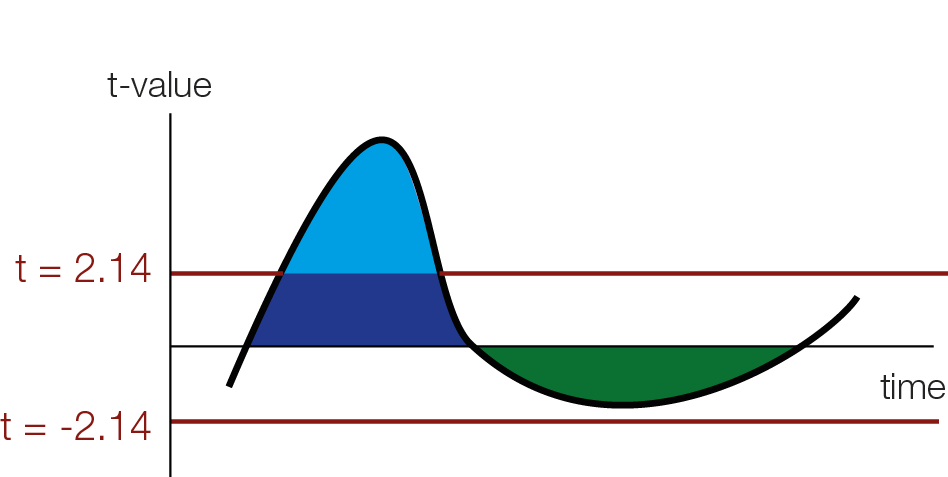
In order to use cluster permutation tests, one typically first calculates some kind of statistics, in our example student t-values for each datapoint over subjects (or trials for single subject analyses). The one has to specify a cluster-threshold which defines the clusters. This threshold might miss broad but “weak” clusters, and focus only on “strong” but peaky clusters.

Threshold Free Cluster Enhancement
The intuition of TFCE is that we are going to try out all possible thresholds and see whether a given time-point belongs to a significant cluster under any of our set of cluster-thresholds. Instead of using cluster mass, we will use a weighted average between the cluster extend (e, how broad is the cluster, i.e. how many connected samples) and the cluster height (h, how high is the cluster, i.e. how large is the t-value / the evidence for an effect) according to the formula:
$$ TFCE = \int_h e(h)^Eh^Hdh$$
for this blogpost, I will put the weights for the extend E and for the height H to 1 (therefore height ‘counts’ the same as width). The usual defaults are E=0.5 and H=2.

As you can see we use a discrete sum, approximating the integral from above. Another difference between TFCE and cluster permutations, is that you generate a TFCE value for each sample.

For instance a hypothetical t-value of 3 (red square in the above animation) is boosted by belonging to a cluster and might receive the TFCE value of 10. The resulting TFCE values can be thought of as a local scaling according to the “clusterdness” of a sample. Note that local minima and maxima stay at the same spot, this is different to a smoothing operation which could move the location of maxima and minima in time or space.

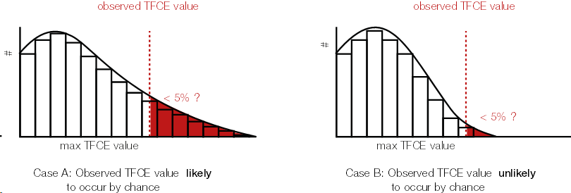
Because we calculated a TFCE value for each sample, we can also calculate a p-value for each sample. In order to get the p-values, we use the same trick wie used with cluster permutation test: the permutation part. We permute conditions (building the $H_0$), calculate the TFCE values for the permutated set, and take the max(TFCE) over all time points and electrodes/voxels. Our observed TFCE value then is either likely or unlikely given our empirical distribution of max TFCE values (under the $H_0$). But note that the interpretation is not that of a typical p-value at an electrodes/voxel!.
Interpretation of significant TFCE
I admit I made the following mistake before, it is a very convenient and easy mistake to make: As an example, let’s observe a significant sample e.g. at 100ms, using the TFCE procedure. This does not mean that the sample at 100ms shows a significant effect. It only means, that there exist at least one cluster-threshold (remember we tested all of them), where this sample belongs to a significant cluster. In other words, samples can be pushed to significance solely by being close to a “truely significant” cluster, without showing evidence by themselves to be significant.
I found this pretty confusing. But in practice it is important: Because we don’t know which samples make a cluster a significant one (all of them? half of them? only a single sample?) we cannot say much about the single sample, only about the cluster.
So, in practice what we do is that we look and report the p-values, but in addition make a descriptive statement on the cluster extend. For instance, you could argue that the t-values that you put in TFCE (or cluster permutation) are very much compatible with an effect from X ms to Y ms. Similar statements are also recommended on the fieldtrip site or in this recent paper by Jona Sassenhagen 2018.
Don’t write: “We found a significant cluster starting from 100ms to 200ms with a median effect of 5µV [3.5, 4.7µV].” or even “Conditions differed significantly from 100ms to 200ms (multiple comparison corrected)”.
Write: “We found a significant difference between conditions. The difference was driven by an effect from 100ms to 200ms with a median effect of 5µV [3.5, 4.7µV] .” or “We found a significant cluster, most compatible with an effect from 100ms to 200ms with a median effect of 5µV [3.5, 4.7µV] “.
Dont write: “At t=125ms the conditions differed significantly (TFCE correction for multiple comparisons) with a median effect of 5µV [3.5, 4.7µV] “
Write: “We found significant difference between conditions (TFCE correction for multiple comparisons). This difference was driven by a cluster starting at 125ms with a median effect of 5µV [3.5, 4.7µV] .”
These messages are much less snappy, sexy, short or easy to understand. The important bit is to signal to the reader that the cluster permutation test does not state significance about a single timepoint or electrode/voxel, but only indicates a significant difference somewhen/re between your conditions.
This problem has been recently discussed on twitter. One proposed alternative is All-Resolution-Inference. There is a barebone R-implementation in the hommel package and I would be interested in translating it to matlab to be readily usable with cluster permutation for EEG data.
Thanks for personal discussions (these are not endorsements, all mistakes in this blogpost are mine!) with Eelke Spaak, Robert Oostenveld, René Scheeringa, Olaf Dimigen & Phillip Alday + twitter interactions with Guillame A Rousselet, Cyril Pernet, Thomas Nichols and Martin Hebart. Thanks to Anna Lisa Gert for critical comments on this blogpost.
Excellent, thx ! just 2 little things
— my interpretation is ‘ It only means, that there exists at least one cluster-threshold (remember we tested all of them), where this sample belongs to a significant cluster’.
— I’d suggest editing, in case people follow literally, adding some effect size reporting – e.g. We found significant difference between conditions (TFCE correction for multiple comparisons). This difference was driven by a cluster starting at 125ms –> We found significant difference between conditions (A. vs. B of 10 uV on average of the cluster 95% CI [6 12]), TFCE correction for multiple comparisons). This difference was driven by a cluster starting at 125ms
Thanks for the comment! I changed it 🙂
Appreciate for the tutorial! I wonder how spatial information is incorporate in calculating TFCE cuz only time-adjacent time-points are considered connected, how about the signals in adjacent channels? How to calculate TFCE considering channels are spatially dependent? Thanks!
There are multiple ways to calculate how channels are spatially connected. Some take the neighbours, some take everything within e.g. 3cm.
You can find examples here: https://www.fieldtriptoolbox.org/faq/how_does_ft_prepare_neighbours_work/
[…] wrote about Threshold-Free-Cluster-Enhancement (TFCE) before, this time I stumbled upon a weirdly looking H0 diagram. Let me explain: If you simulate data […]
Thank you for your excellent tutorial! I’ve been applying this method to some EEG data and have encountered an interesting situation that I’d appreciate your opinion on.
In an analysis, I’ve observed two temporal positive clusters of significant p-values, e.g.:
First cluster: 100-300ms
Second cluster: 310-500ms
These clusters are separated by a brief 10ms gap (approximately 4 samples) where no electrodes show significant p-values. Given the topographical patterns and the extremely short duration of this interruption, I would suspect these might actually represent a single process instead of two separate components. However, I’m curious about the best practices for handling such situations. Is there any recommendation you could give?
Thank you very much, and best regards!
I think setting-up and testing hypothesis is a separate step from the actual interpretation. Given the reasons you state, I see no problem in just lumping them together!